
Guest Post by Mr. Agastiya Venkata Ranuva, Technical Manager, BEACON
This study is used to examine the stress in a pressure vessel by combing the results of static studies with desired factors. Each study has a different set of loads that produce corresponding results. The type of loads can be dead loads, live loads, thermal loads, seismic loads, etc., In this study, all these study results combine algebraically using a linear combination or the square root of the sum of the squares (SRSS).
When the study is performed using the solid mesh, the user can use stress linearization tool which separates bending and membrane components.
Important considerations in performing the study:
- Only loads can be varied, rest of the properties should remain identical to combine the studies.
- Solution is valid only if the results are in linear range i.e., studies should not use either large displacement or no penetration contact in the analysis.
- Since this functionality is vastly used in the design of pressure vessels, design and manufacturing codes are required to combine certain load scenarios.
- The software uses the existing results from the selected studies and combines them.
- During calculation of resultant displacement, von mises and principal stresses, the software first combines the directional components.
- When using SRSS, the displacement plots cannot be created as the negative displacements will become positive when squared.
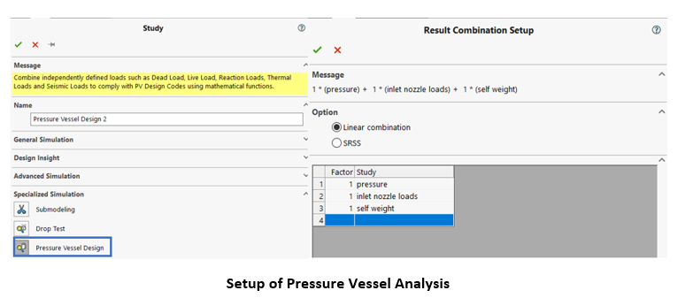
Results Combination Setup
This step lets the user to setup the study using either linear combination or SRSS method.
- Linear combination – Creates an algebraic equation to combine the results from selected studies.
- SRSS – Combines the results from the selected studies by applying the square root of the sum of the squares.
- Factor – It’s a multiplication factor for a study to vary the load. (Only in Linear comb.)
- Study – User needs to select at least two studies to combine. Later, no. of studies can be either added or deleted.
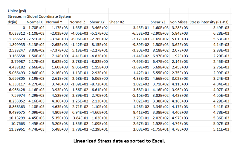
Stress Linearization
This tool is used to separate the bending and membrane stresses from the actual stress distribution throughout the thickness of the wall in a sectional stress plot and works in accordance with the American Society of Mechanical Engineers (ASME) International Boiler and Pressure Vessel Code ASME BPVC-VIII-2.
This is used for solid meshes only. For shell mesh, the user has to plot and list membrane and bending stresses separately.
This concept provides an idealization of the actual stress variation throughout the thickness of the wall. A membrane stress is constant through the thickness, whereas a bending stress is varied linearly. Non-linearized stress is referred as the Peak stress.
The following figure shows the concept of stress linearization.
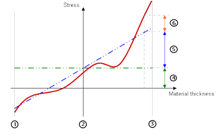
1 – Inner wall boundary
2 – Midplane
3 – Outer wall boundary
4 – Membrane stress component (Green dotted line)
5 – Bending stress component (Blue dotted line)
6 – Peak stress (Red solid line, actual stress)
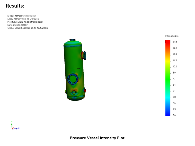
An Example of Pressure Vessel Analysis in SOLIDWORKS Simulation
Setup:
To perform the Pressure vessel analysis, It is important to perform individual studies like Thermal, Structural analysis, etc., and save the results. These studies will be utilized to perform the Pressure Vessel Analysis to understand the behavior of the Pressure Vessel.
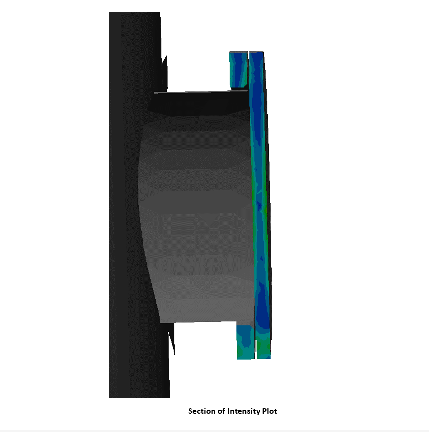
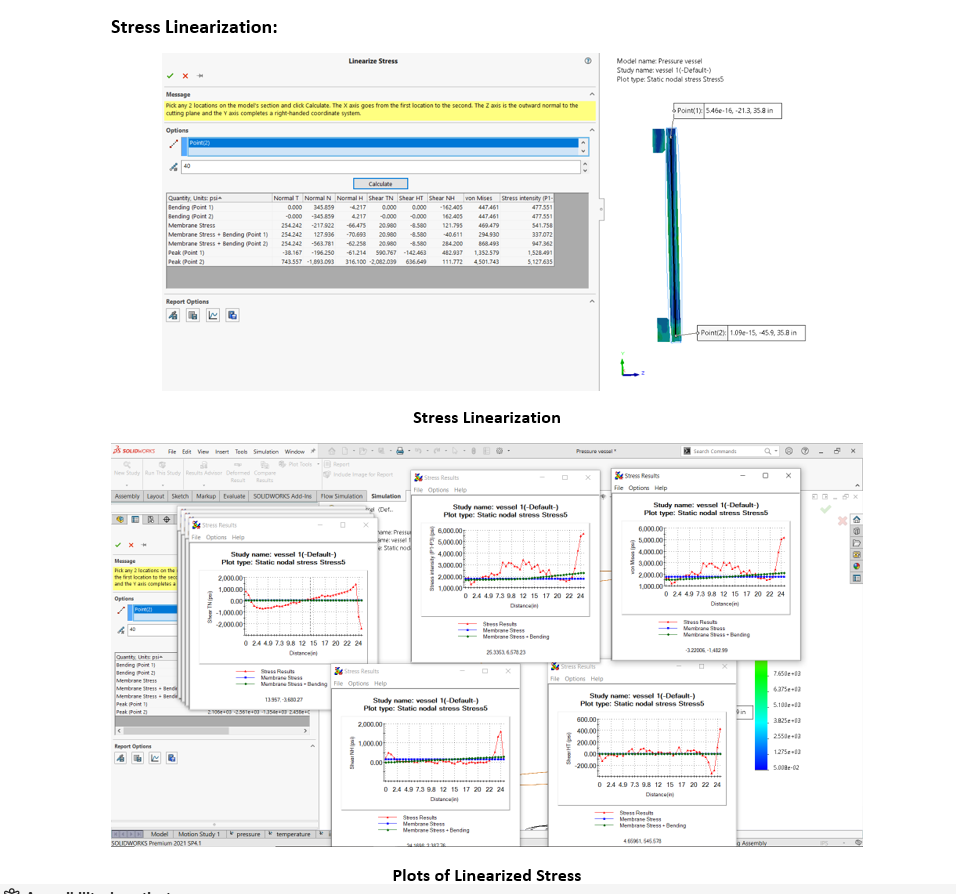
This way SOLIDWORKS Simulation can help the engineers in extracting the Linearized Stress values from the solid itself and can be used to validate with respect to the Pressure Vessel and Boiler standard codes.
Guest Post by Mr. Agastiya Venkata Ranuva, Technical Manager, BEACON

")